Nikola Tesla's Tesla Coil
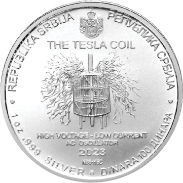
In 1891, the electrical genius Nikola Tesla invented his first Tesla Coil. Later versions expanded on these High-Voltage - Low Current AC Oscillators. The devices can transmit lightning-like amounts of electricity through the air to power electrical devices. |
SYSTEM OF ELECTRIC LIGHTING.
N0. 454,6 22. Patented June 23,1891.
UNITED STATES PATENT QFFICE.
NIKOLA TESLA - OF NEW YORK, N. Y.
SYSTEM OF ELECTRIC LIGHTING.
SPECIFICATION forming part of letters Patent No. 454,622, dated June 23, 1891.
Application filed April 25, 1891.
To all whom it may concern..-
Be it known that I, NIKOLA TESLA, a sub ject of the Emperor of Austria-Hungary, from Smilj an, Lika, border country of Austria-Hungary, and a resident of NewYorkJnthe county vices, such as, electric lamps, and, second,
that currents of high potential have also been produced and employed for obtaining luminous effects, and this, in a broad sense, may.
be regarded for purposes of this case as the prior state of the art; but Ihave discovered that results of the most useful character may be secured under entirely practicable conditions by means of electric currents in which both the above-described conditions of high frequency and great difference of potential are present. In other words, I have made the discovery that an electrical current of an excessively small period and very high potential may be utilized economically and praci'icably to great advantage for the production of light.
It is difficult for me to define the exact limits of frequency and potential within which my discovery is comprised, for the. results obtained are due to both conjointly; but I would make it clear that as to the inferior limits ofboth, the lowest frequency and potential that I contemplate using-are far above what have heretofore been. regarded as practicable. As an instance of what I regard as the lowest practicable limits I would state that I have obtained fairly good results by a frequency as low as fifteen thousand to twenty thousand per second and a potential of about twenty thousand volts. Both frequency and potential may be enormously increased above these figures, the practical limits being determined by the character of the apparatus and its on- Serial No. 390,414. (No model.)
producing the currents or electrical effects of the character described; second, a novel method of utilizing and applying the same for the production of light, and, third, a new 7 form of translating device or light-giving appliance. These I shall now describe. To produce acurrent of very high frequency .and very high potential, certain well-known devices may be employed. For instance, as the primary source of current or electrical energy a continuous-current generator may be used, the circuit of which may be interruptcd with extreme rapidity by mechanical devices, or a magneto-electric machine specially constructed to yield alternating currents of very small period may be used, and in either case, should the potential be too low, an induction-coil may be employed to raise it; or, finally, in order toovercome the mechanical difiiculties, which in such cases become practically insuperable before the best results are reached, the principle of the disruptive discharge may be utilized. iy means of this latter plan I producea much greater rate of change in the current than by the other means suggested, and in illustration of my invention I shall confine the description of the means or apparatus for producing the current to this plan, although I would not be understood as limiting myself to its use. The current of high frequency, therefore, that is necessary to the successful working of my invention I produce by the disruptive discharge of the accumulated energy of a condenser maintained by charging said condenser from a suitable source and discharging it into or through a circuit under proper-relations of self-induction,capacity, resisti'mcemndperiod in well-understm N1 ways. Such a discharge I8 known to be, under proper conditions, intermittent or oscillating in character, and in this Way a current varyingin strength at an errorrnously rapid rate maybe produced. Having produced in the above manner a current of excessive frequency, I obtain from it by, means oi an induction-coil enormously high potentials-that is to say, in the circuit through which or intoivvhich the disruptive discharge of the condenser takes place i include the primary of a suitable induction-coil, and by a secondary coil of much longer and finer wire 1 convert to currents of extremely high potential. The di'fierences in the length of the primary and secondary coils in connection with the enormously rapid rateoi change in the primary current yield a secondary of enormous frequency and excessively high potential, Such currents are not, so far as l am aware, available for use in the usual Ways; but 1 have discovered that if ll connect to either of the terminals of the secondary coil or source of I current of high potential the leading' in Wires of such a device, for example, as an-ordh nary incandescent lamp, the carbon may be brought to and maintained at incandescence, or, in general, that any body capable oi con ducting the high-tension current described and properly inclosed in a rarefied or exhausted receiver may be rendered luminous or incandescent, either when connected di-= rectly with one terminal or the secondary source or energy or placed in the vicinity of such terminals so as to be acted upon induct ively.
Without attempting a detailed explanation of the causes to which this phenomenon may be ascribed, ll deem it sufiicient to state that, assuming the now generally accepted theories of scientists to be correct, the edects thus produced are attributable to molecular bombardment, condenser action, and electric or etheric disturbances. Whatever part each or any of these causes may play in producing the efiects noted, it is, however, a fact that a strip of carbon or a mass oi any other shape, either of carbon or any more or less conduct= ing substance in a rarefied or exhausted receiverand connected directlyor inductively to a source of electrical energy such as l have described, may be maintained at incandescence if the frequency and potential of the current be sufficiently high, F I would here state that by the termsfcur rents of high frequency and high potential and similar expressions which I have used in this description I do not i mean, necessarily, currents in thensual acceptance of the term, but, generally speaking, electrical disturbances or efiects such as would be produced in the secondary source by the action of the primary disturbance or electrical eiiiect.
It is necessary to observe in carrying out this invention that care must be taken.- to reduce to a minimum the opportunity for the dissipation of the energyfrom the conductors ondary.. desired, one terminal may walls should be coated with conducting substance in order that they may intermediate to the source of current and the light-giving body For this purpose the conductors should be free from projections and points and well covered or coated with a good insulator.
The body to be rendered incandescent should be selected with a view to its capability of withstanding the action to which it is exposed without being rapidly destroyed, for some conductors will be much more speedily consumed than others,
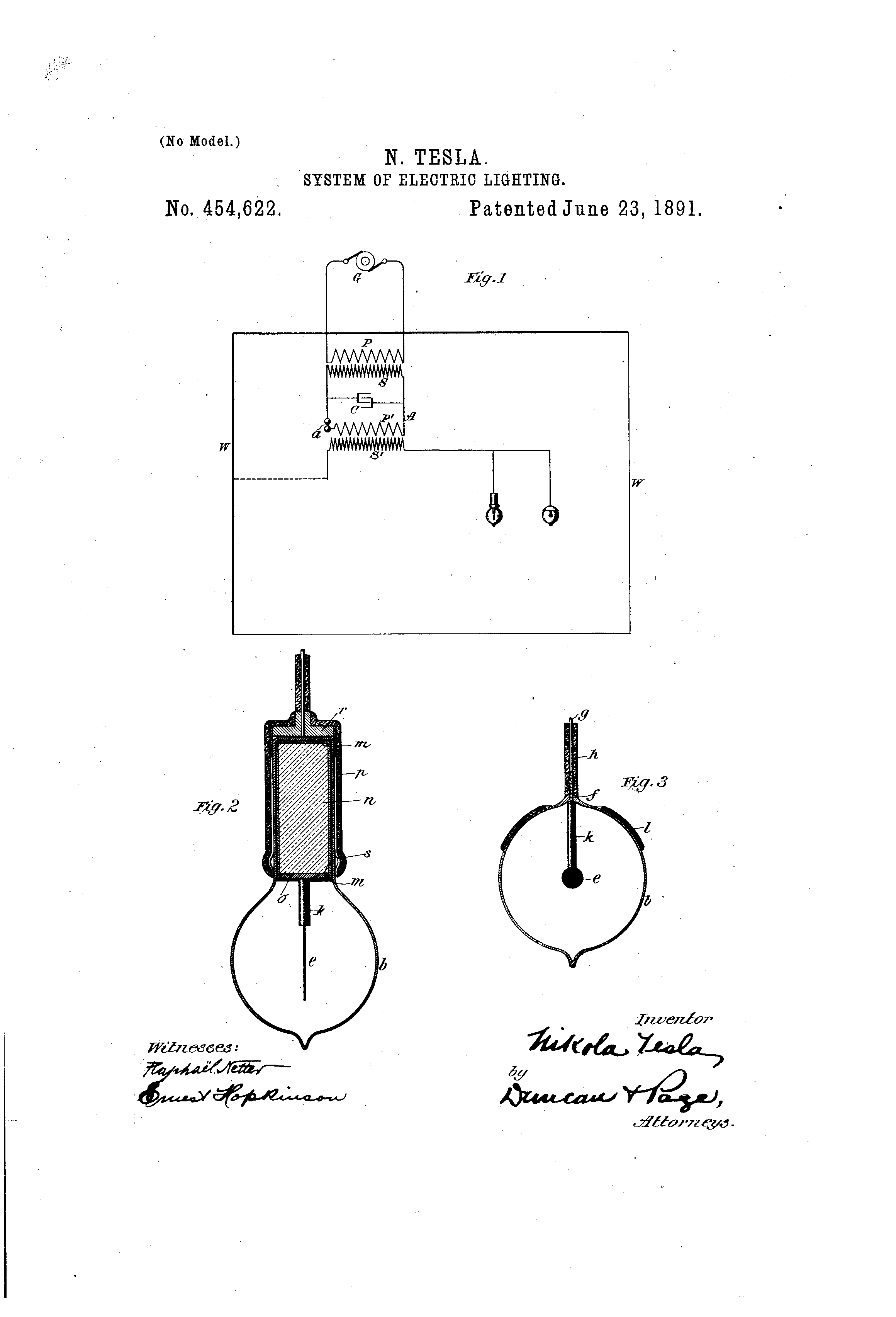
1' now refer to the accompanying drawings, in which- Figure 1 is a diagram of one of the special arrangements that l have employed in carrying out my discovery, and Figs. 2 and 3 are vertical sectional views of modified forms of light-giving devices that l have devised for use with the system.
I would state that as all of the apparatus herein shown, with the exception of certain specialforms of lamp invented by me, is or may be of well-known construction and in common use for other purposes, l have indicated such Well-known parts therefor by con ventional representations. 7 G is the primary source of current or elec trical energy. I have explained above how various forms of generator might be used for this purpose; but in the present illustration I. assume that G is an alternating-current generator of com parativelylow electro-inotive force. Under such circumstances I raise the potential of the current by rneansot an induction-coil having a primary P and a secondary S. Then by the current developed in this secondary I charge a condenser O, and this condenser I discharge through or into a circuit A, having an air-gap a, or, in general, means for maintaininga'disruptive discharge, By the means above described a current of enormous frequency is produced. My object is next to convert this into a working-circuit of very high potential, for which purpose it connect up in the circuit .A the primary P of an induction-coil having a long fine wire sec- The currentin trical efiect of corresponding frequency, but of enormous difference of potential, and the secondary S thus becomes the source of the energy to be applied to the purpose ofp rm ducing light.
The light-giving devices may be connectedto either terminal of the secondary S. It dcconducting-wall W of a room or space to be lighted and the other arranged for con nection of the lamps therewith. In such case the some metallic or have 'suflicient conductivity.
The lamps or light-giving devices may be an ordinary incandescent lamp; but I prefer t0 use specially-designed lamps, examples of which I have shown in-detail the draw be connected to a the primary 1 develops in the secondary S a current or elec lill . the interior of the neck of the globe, and ings. This lamp consists of a rarefied 'or exhausted bulb or globe which incloscs a refractory conducting body, as carbon, of comparatively small bulk and any desired shape. This body is to be connected to the secondary by one or more conductors sealed in the glass, as in ordinary lamps, or is arranged to be inductively connected thereto. For this last-named purpose the body is in electrical contact with a metallic sheet in on the outside of said neck is a second sheet which is to be connected with the source of current. These two sheets form the arma tures of a condenser, and by them the currents or potentials are developed in the light giving body. As many lamps of this or other kinds may be connected to the terminal of S as the energy supplied is capable of maintain ing at incandescence.
In Fig. 3, b is a rarefied or exhausted glass globe or receiver, in which is a body of carbon or other suitable conductor 6. To this body is connected a metallic conductor j, which passes through and is sealed in the glass wall of the globe, outside of which it is united to a copper or other wire g, by means of which it is to be electrically connected to one pole or terminal of the source of current.
Outside of the globe the conducting-wires are protected by a coating of insulation 72', of any suitable kind, and inside the globe the supporting-wire is inclosed in and insulated by a tube or coating It of a refractory insulating substance, such as pipe-clay or the like. A reflecting-plate Z is shown applied to the outside of the globe b. This form of lamp is a type of those designed for direct electrical metallic plate 0, . is electrically connected by connection with one terminal of the source of current; but, as above stated, there need not be a direct connection, for the carbon or other illuminatingbody may be renderedluminous by inductive action of the current thereon, and this may be brought about in several ways. The preferred form of lamp for this purpose, however, is shown in Fig. 2. In this figure the globe b is formed with a cylindrical neck, within which is a tube or sheet m of conducting material on the side and over the end of a cylinder or plug it of any suitable'insulating material. The lower edges of this tube are in electrical contact with a secured to the cylinder 01, all the exposed surfaces of such plate and of the other conductors being carefully coated and protected by insulation. The light-giving body e, in this case a straight-stem of carbon, with the said plate a-wire or conductor similar to the wire f, Fig. 3, which 'is.coated in like manner with a refractory insulating material It. The neck bf the globe fits into a socket composed of. an insulating tube or cylinder 11, with a more or less complete metallic linlng s, electrically connected by a metallic head or plate rwith a conductor g, that is to be attached to one pole of the source of current. The metallic lining 8 and the sheet on thus compose the plates or armaturcs of a condenser.
This invention is not limited to the special means described for producing the results hereinabove set forth, for it will be seen that. various plans and means of producing currents of very high frequency are known, and
also means for producing very high poteutials; but I have only described herein certain ways in which I have practically carried out the invention.
that I claim is-
1. The improvement in the artof electric lighting herein described, which consists in generating or producing for the operation of the lighting devices currents of enormous frequency and excessively high potential, substantially as herein described.
2. The method of producing an electric current for practical applicatiomsuch as for electric lighting, which consists in generating or producing a current of enormous frequency and inducing by such current in a working circuit, or that to which the lighting devices are connected, a current of corresponding frequency and excessively high potential, as set forth.
3. The method of producing an electric current for practical application, such as for electric lighting, which consists in charging a condenser by a given current, maintaining an intermittent or oscillatory discharge of said condenser through or into a primary circuit, and producing thereby in a secondary working-circuit in inductive relation to the primary very high potentials, as set forth.
4. The method of producing electric light by incandescence by electrically or inductively connecting a conductor inclosed in a rarefied or exhausted receiver to one of the .poles or terminals of a source of electric rco energy or current of a frequency and potential sufficiently high to render said body incandescent, as set forth.
5. A system of electric lighting, consisting in the combination, with a source ofv electric energy or current of enormous frequency and excessively high potential, of an incandescent lamp or lamps consisting of. a conducting body inclosed in a rarefied or exhausted receiver and connected directly or inductively to one pole or terminal of the source of energy, as set forth.
6. In a systemof electric lighting, the combination,with a source of currents of enormous frequency and excessively high potential, of incandescent lighting devices, each consisting of a conducting body inclosed in a rarefied or exhausted receiver, said conducting body being connected directly or inductively to one pole or terminal of the source of current, and a conducting body or bodies in the vicinity of said lighting devices connected to the other pole or terminal of said source, as set forth.
eseeee 70 in e: sysiem of electric lighting, the combination, with seen... of enermous frequency of excessively high potential, of fighting devices each... in a rarefied or exhausted receiver and... directly or influctively with... of said... intermediate to the said source and the light-giving" body-being insulated. and protested to prevent the dissipation of the e1ectrio energy, as herein set forth.
 NIKOLA TESLA- Witnesses:
PARKER W. PAGE, G. TRACY.


